Tag: Azure Data Factory

Why I Prefer Hand-Coded Transformations over ADF Mapping Data Flow

Firstly, I need to clarify that what I am discussing in this blog post is only with ADF Mapping Data Flow instead of the whole ADF service. I am not going to challenge ADF’s role as the superb orchestration service in the Azure data ecosystem. In fact, I love ADF. At the control flow level, it is neat, easy to use, and can be very flexible if you can be a little bit creative and imaginative. To avoid potential confusion, I define the “Hand-Coded Transformations” and the “ADF Mapping Data Flow” in this blog post as:

  • Hand-Coded Transformations – Programming transformation logics in code (pyspark, SQL, or others) and orchestrating the execution of the code using ADF data transformation activities in control flow, such as Databricks activities, Stored Procedure activity, and custom activity.
  • ADF Mapping Data Flow – Programming transformation logics using ADF Mapping Data Flow visual editor.

I totally understand why people prefer using a GUI-based, ready-to-use, code-free ETL tool to manually crafting data wrangling/transforming code. Intuitively, this is a no-brainer choice for people who view it from 10,000 feet. However, the devil is in the details. Here is the list of reasons why I prefer hand-coded transformation to ADF Mapping Data Flow:

  • One of the main drives for using ADF Mapping Data Flow is possibly the simplicity and flat learning curves. This may be true for the simple, generic transformation logic. However, for the more complicated, domain-specific requirements, ADF Mapping Data Flow does not have to be simpler than writing code in SQL or Python. They either require you to create complex data flow logic or you have to embed custom code in the data flow eventually. On the other hand, the hand-coded approach can be much simpler due to the flexibility of custom coding and the huge number of ready-to-use data wrangling/transformation libraries.
  • You may argue that the ADF Mapping Data Flow is for people who don’t know coding. However, ADF does not play the role of self-service ETL tools in the Azure data ecosystem (Power Query does). The target users of ADF should be data engineers or DataOps instead of data analysts. I understand some junior data engineers may resisting coding and shy away even without a try. The ADF Mapping Data Flow gives them the opportunity to escape and actually deprives their motivations of learning coding.
  • We can implement some validation logics in an ADF Mapping Data Flow, but that would be very high-level and simple. That does not allow us to conduct a comprehensive unit test on the transformation logics.
  • One of the main reasons I prefer coding over visual editor is the reusability, including reusability of domain-specific business logics and reusability of domain-independent non-functional logics, such as auditing, QA and exception handling. As the ADF Mapping Data Flow is working in the declarative paradigm, it is difficult to abstract and generalise the logic implemented in ADF Mapping Data Flow. On the other hand, abstraction and generalisation can be easily implemented with custom coding.
  • Custom coding allows you to build configurable and metadata-driven pipelines. A configurable, metadata-driven design can significantly improve the maintainability of your ADF pipelines. One of my previous blog posts describes some of my early designs of metadata-driven ADF pipelines with custom coding in SQL. If you are interested, you can find the blog post here.
  • The last but also the most important reason for me to favour hand-coded approach is the control and flexibility I can have to withstand the uncertainty in my projects. Just like any other IT project, it is not realistic to predict and control all the possible situations in a data engineering project. There are always some kinds of surprises popping up or user requirement changes. A code-free tool like ADF Mapping Data Flow hides the implementation under the hood and requires you to work in their way. In case an unpredicted situation happens and the code-free tool cannot handle it, it is expensive to change the tool at a late stage of a project. Compared to a code-free tool, hand-coding give you more flexibility and resilience to handle unpredicted situations.

Configuration-Driven Azure Data Factory Pipelines

In this blog post, I will introduce two configuration-driven Azure Data Factory pipeline patterns I have used in my previous projects, including the Source-Sink pattern and the Key-Value pattern.

The Source-Sink pattern is primarily used for parameterising and configuring the data movement activities, with the source location and sink location of the data movement configured in a database table. In Azure Data Factory, we can use Copy activity to copy an data entity (database table or text-based file) from a location to another, and we need to create an ADF dataset for the source and an ADF dataset for the sink. It can easily turn into a nightmare when we have a large number of data entities to copy and we have to create a source dataset and a sink dataset for each data entity. With the Source-Sink pattern, we only need to create a generic ADF dataset for each data source type, and dynamically refer to the data entity for copy with the source and sink settings configured in a separate configuration database.

The Key-Value pattern is used for configuring the settings of activities in Azure Data Factory, such as the notebook file path of a Databricks Notebook activity or the url of a logic app Https event. Instead of hard-coding the settings in ADF pipeline itself, the Key-Value pattern allows to configure the activity settings in a database table and to load the settings and dynamically apply them to the ADF activities at runtime.

In the rest of this blog post, I will introduce the implementation of those two patterns in Azure Data Factory.

Source-Sink Pattern

To implement the Source-Sink pattern in Azure Data Factory, the following steps need to be followed:

  • Step 1 – create data movement source-sink configuration table
  • Step 2 – create generic source and sink datasets
  • Step 3 – use Lookup activity to fetch the source-sink settings of the data entities for copy from the configuration table
  • Step 4 – use ForEach activity to loop through the data entities for copy
  • Step 5 – add a generic Copy activity inner the ForEach activity

Step 1 – create data movement source-sink configuration table

Create a configuration database (an Azure SQL database will be a good option), and create a table with columns to define data movement category, location for source and location for sink.

ADF_04_001

Along with the configuration table, we need to create a stored procedure for the Lookup ADF activity to retrieve the source-sink settings of the data entities for specified copy category.

ADF_04_020

Step 2 – create generic source and sink datasets

Create generic source and sink datasets. To make the datasets generic, we need to create a number of dataset parameters to define the location of the table or file referred by the dataset. Those parameters will take the values fetched from the configuration database table at runtime.

ADF_04_005

On the Connection tab of the generic dataset, we need to specify the table name or file container/path/name using the dataset parameters we just defined.

ADF_04_006

Step 3 – use Lookup activity to fetch the source-sink settings 

Add a Lookup activity and set to use the stored procedure we created earlier for retrieving the source-sink settings of all the data entities for copy in a specified category.

ADF_04_019ADF_04_007

The output of the Lookup activity will contains source-sink settings of all the data entities in the specified category defined in the configuration database table.

ADF_04_017

Step 4 – use ForEach activity to loop through the data entities for copy

Add and chain a ForEach activity after the Lookup activity, and set the Items property of the ForEach activity as the output of the Lookup activity, @activity(‘Lookup Configuration’).output.value, so that the ForEach activity will loop through the source-sink settings of all the data entities fetched from the configuration database table.

ADF_04_009

Step 5 – add a generic Copy activity inner the ForEach activity

Inner the ForEach activity, add the Copy activity with the Source and Sink pointing to the generic source dataset and sink dataset we created earlier and pass the corresponding source-sink settings of current data entity item, such as @item().Sink_Item for the file name of the sink.

ADF_04_010

At this point, the source-sink pattern is all set. When the pipeline runs, a copy channel is created and executed for each data entity defined in the configuration database table.

ADF_04_011

Key-Value Pattern

To implement the Key Value pattern in Azure Data Factory, the following steps need to be followed:

  • Step 1 – create activity settings key-value configuration table
  • Step 2 – create stored procedure to transform the key-value table
  • Step 3 – use Lookup activity to retrieve activity settings from configuration table
  • Step 4 – apply settings on ADF activities

Step 1 – create activity settings key-value configuration table

Create a database table with columns defining pipeline name, activity type, activity name, activity setting key, activity setting value.

ADF_04_012

Step 2 – create stored procedure to transform the key-value table 

The ADF Lookup activity is not working in the key-value type dataset. Therefore, we need to convert the key-value table into a single data row with column header as the activity setting key and the column value as the activity setting value.

ADF_04_013

We can use T-SQL PIVOT operator to convert the key-value table into the single row table. However, as the number of records in the key-value table is not fixed, we cannot specify the keys for pivot. Instead, we need to fetch the keys from the key-value table first and author the PIVOT operation in dynamical sql. The snapshot below shows the stored procedure I have created for convert the key-value table.

ADF_04_014

Step 3 – use Lookup activity to retrieve activity settings from configuration table

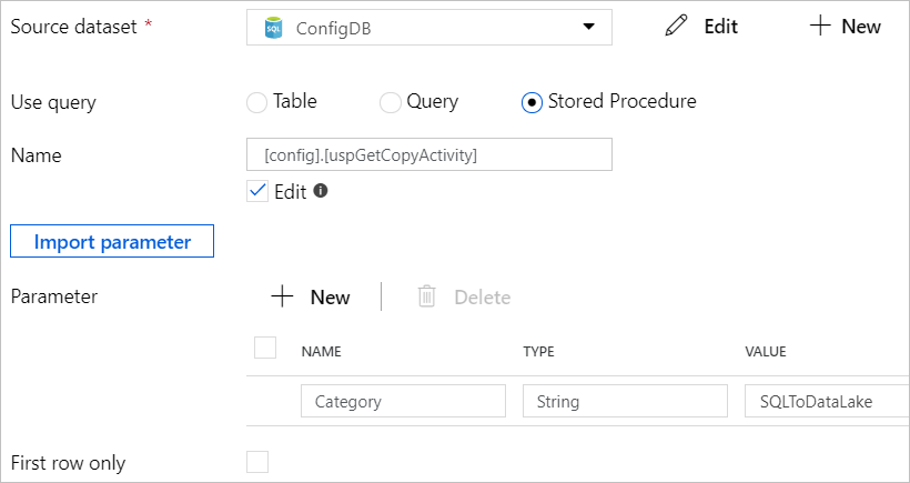
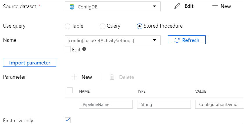
In the Azure Data Factory pipelines you are creating, at the start of the activities chain, Add a Lookup activity and use the stored procedure created earlier to retrieve the key-value table and convert it into the single row format to be readable for the Lookup activity.  On the Lookup activity, tick the ‘First row only’ on as the result of the Lookup activity will be the single row dataset.

ADF_04_015

The snapshot below shows what the output of the Lookup activity looks like.

ADF_04_016

Step 4 – apply settings on ADF activities

From the output of the Lookup activity, the other ADF activities chained after can access the value of an activity setting as @activity(‘{lookup activity name}’).output.firstRow.{column name for the key}. 

ADF_04_018

Execute R Scripts from Azure Data Factory (V2) through Azure Batch Service

Introduction

One requirement I have been recently working with is to run R scripts for some complex calculations in an ADF (V2) data processing pipeline. My first attempt is to run the R scripts using Azure Data Lake Analytics (ADLA) with R extension. However, two limitations of ADLA R extension stopped me from adopting this approach. Firstly, ADLA R extension supports only one input dataframe and one output dataframe at the time when I write this blog post. However, the requirement I am working with needs the R scripts to take multiple dataframes as input and output multiple result dataframes. Secondly,  the total size for the input and output is limited to 500 MB.

Another attempt I have taken was to create an ADF custom activity to execute the R scripts in Azure Batch Service. This option turns out to be a pretty flexible, easy to implement and manage approach.

Approach

This blog post highlights the key steps to implement this approach and also mentions the lessons I have learnt.

Step 1 – Preparing Azure Batch Service

Firstly, we need to add an Azure Batch pool in an Azure Batch service instance. If the Azure Batch service instance doesn’t exist yet, a new instance needs to be provisioned. Please refer to Microsoft official docs for the details on creating Azure Batch service and pools.

While adding the Azure Batch pool, we need to specify the VM image to provision as the computing nodes in the pool. We can use Data Science Virtual Machine image which ships with most of common R packages.

Capture1.PNG

Step 2- Creating Container in Azure Blob Storage to Host R Source Files and Input/Output Data

Create a Blob storage container in your Azure Storage account and then create an Input folder and an Output folder within the container root folder.

The R source files will be deployed into the container root folder. The input data files are the output of the upstream process activities in the ADF pipeline and pushed (copied) into the Input folder. The R source files and the input data files will be submitted to execute in the Azure Batch service (by the Azure Batch custom activity which will be created later in the ADF pipeline), the output will be written into the Output folder in the Azure Blob storage.

Step 3 – Authoring R Scripts to Communicate with the Azure Blob Storage

When the Azure Batch custom activity is triggered in the ADF pipeline, the R source files and the input data files will be submitted into the work directory created for the submitted task on the Azure Batch computer nodes. The R scripts will load the data in the data files into dataframes, run the calculations and transformations, and finally write the results to output data files and store them in the work directory. The output data files will then be written into the Output folder in the Azure Blob storage using the blob operation functions provided by rAzureBatch package. Here is a good sample from the doAzureParallel Github site on the blob operations with rAZureBatch.

Basically, we need first to create a rAzureBatch StorageServiceClient with the Azure Storage account credentials.

storageCredentials <- rAzureBatch::SharedKeyCredentials$new(
    name = "{name of the Azure Storage account}",
    key = "{access key of the Azure storage account }"
)

storageClient <- rAzureBatch::StorageServiceClient$new(
   authentication = storageCredentials,
   url = "{url of the Azure Blob storage}"
)

Then, we need to create a SAS token with write permission on the Output folder

writeSasToken <- storageClient$generateSasToken(permission = "w", "c", path = {the path of the Output folder})

Lastly, we can save the output file into the Output folder on Azure Blob storage with the uploadBlob function.

response <- storageClient$blobOperations$uploadBlob(
    containerName,
    fileDirectory = "{output file name}",
    sasToken = writeSasToken,
    accountName = storageAccountName)
if (response[['status_code']]!=201) {
    stop('Failed to save the output file.')
}

It is important to explicitly check the response status_code and throw error when the save action is failed. Otherwise, the ADF pipeline will not able to capture the error but instead treat the custom activity as running successfully and move on to the downstream activities.

Step 4 – Setup Azure Batch Custom Activity in ADF Pipeline

After the Azure Batch service part of work is done, we need to add and configure the Azure Batch Custom Activity in ADF Pipeline. This step is pretty straightforward, please refer to the Microsoft official docs for the more details. The only part needs to note is the settings of “Command” and “Folder path” of the Azure Batch Custom Activity. The “Command” should be “RScript {the entry R file you want to run}”, and the “Folder path” should be the container we have created earlier to host the R source files.

b

Those are the four main steps to setup the execution of R scripts in ADF pipelines.

Below lists a few of tips that might be helpful:

If you need to install additional R packages for your scripts, specify the lib path with the environmental variable, AZ_BATCH_TASK_WORKING_DIR,  in order to install the packages into the working directory of the current task. Please refer to my previous blog post for further explanation.

 install.packages("tidyselect", lib=Sys.getenv("AZ_BATCH_TASK_WORKING_DIR"))

If the Azure Batch Custom Activity throw an UserError with message as “Hit unexpected expection and execution failed.”, you can find the detailed error message from the stderr.txt file on the working directory of the failed task.

Capture

To access the working directory, you need to go to the Azure Batch account –> Jobs –>  select job –> select the failed task, and select “Files on node”.

Capture01

Then you should be able to see all the files existing on the working directory of that task, including the stderr error output file.

Capture02.PNG


SSIS in Azure #3 – Schedule and Monitor SSIS Package Execution using ADF V2

*The source code created for this blog post can be found here.

In the previous blog posts in the SSIS in Azure series, we created a SSIS package to periodically ingests data from Azure SQL database to Azure Data Lake Store and deployed the package in the Azure-SSIS Integrated Runtime. Up to this point, we have achieved two goals in the SSIS in Azure series:

  • Using SSIS to move data between cloud storages
  • Host and run SSIS packages in cloud

The last goal we need to achieve is to schedule the execution of the SSIS package in cloud. Traditionally, we can schedule the SSIS package execution by creating a SQL Server Agent job. However, we can only do that through an on-premises SQL Server instance or provision a SQL Server vm in Azure. Thanks to the support of Stored Procedure activity in ADF, we can now schedule the SSIS package execution using a cloud-based ADF pipeline. This blog post will walk through the steps to achieve that.

You can find the source code created for this blog post in my Github. The ningago.demo.adf.ssis.adfv2 project contains the json and powershell files to create the ADF pipeline.

4.PNG


The key to this solution is to call the sp_executesql stored procedure in the RunSSISPackagePipeline pipeline that execute the sql script for triggering the SSIS package execution. We can define a Stored Procedure activity in the pipeline to call the sp_executesql stored procedure and pass in the sql script for triggering the SSIS package execution as parameter.

5

We don’t have to manually author the sql script from scratch, but instead we can generate the script using SSMS. First, we connect to the SSISDB catalog in our Azure-SSIS integrated runtime (please refer to SSIS in Azure #2 for how to do that), select the SSIS project or package we can execute, and click the Execute button to open the Execute Package dialog window.

6

On the Execute Package dialog window, we select the package to execute and also set a value (can be any value) for the package parameter (the reason is set any value to the parameter is to ensure the parameter setting statement will be generated in the sql script).

2

We then click the “Script” button on the top-left that will generate the sql script for executing the selected SSIS package.

3

We can then copy the script into the stored procedure activity defined in the RunSSISPackagePipeline pipeline.

5

As you may have noticed that the SSIS package parameter, DateScliceToLoad, has been manually set by us with a random value. The next step we need to take is to pass the date of pipeline run into the sql script in order to make the SSIS package only move the data in the give day. Firstly, we need to define the “scheduledRunTime” parameter in the RunSSISPipeline which will receive the scheduled pipeline run time from the pipeline trigger we will create later.

6.PNG

In the sql script we just generated to trigger SSIS package execution, we replace the random date we have manually set with the ADF expression which points to the scheduleRunTime parameter in the pipeline.

7.PNG

Next, we will need to create the trigger json file to schedule the execution of the pipeline. After we specify the pipeline to execute in the trigger file, we need to pass the scheduledTime of the trigger which is a system variable to the scheduledRunTime parameter defined in the pipeline.

{
  "properties": {
    "name": "RunSSISPackageScheduler",
    "type": "ScheduleTrigger",
    "typeProperties": {
      "recurrence": {
        "frequency": "Hour",
        "interval": 1,
        "startTime": "2018-01-07T00:00:00-22:00"
      }
    },
    "pipelines": [
      {
        "pipelineReference": {
          "type": "PipelineReference",
          "referenceName": "RunSSISPackagePipeline"
        },
        "parameters": {
          "scheduledRunTime": "@trigger().scheduledTime"
        }
      }
    ]
  }
}

After we have created the json files to define linked service, pipeline and the trigger, we need to deploy them into our data factory instance. As the V2 version of ADF does not support deployment through UI yet, we need to create a deployment scripts using PowerShell.

$DataFactoryName = "ninjago3843adf"
$ResourceGroupName = "SSIS"

Set-AzureRmDataFactoryV2LinkedService -DataFactoryName $DataFactoryName -ResourceGroupName $ResourceGroupName -Name "SSISDBLinkedService" -File ".\SSISDBLinkedService.json"
Set-AzureRmDataFactoryV2Pipeline -DataFactoryName $DataFactoryName -ResourceGroupName $ResourceGroupName -Name "RunSSISPackagePipeline" -DefinitionFile ".\RunSSISPackagePipeline.json"

Stop-AzureRmDataFactoryV2Trigger -ResourceGroupName $ResourceGroupName -DataFactoryName $DataFactoryName -Name "RunSSISPackageScheduler"
Set-AzureRmDataFactoryV2Trigger -ResourceGroupName $ResourceGroupName -DataFactoryName $DataFactoryName -Name "RunSSISPackageScheduler" -DefinitionFile ".\RunSSISPackageScheduler.json"
Start-AzureRmDataFactoryV2Trigger -ResourceGroupName $ResourceGroupName -DataFactoryName $DataFactoryName -Name "RunSSISPackageScheduler"

After the pipeline is deployed and scheduled by the trigger, the pipeline will execute our SSIS package based on the schedule.

8.PNG


SSIS in Azure #2 – Deploy SSIS Packages to Azure-SSIS Integration Runtime in ADF V2

In the first blog post of the SSIS in Azure series, I gave a demonstration on how to create SSIS packages to move data in cloud, using a common use case that periodically ingests data from Azure SQL database to Azure Data Lake Store.  In the pre-ADF V2 era, we can only deploy SSIS packages in on-premises SQL Servers or SQL Servers in Azure VM. Thanks to the Azure-SSIS integration runtime that is available for public preview in Azure Data Factory V2, we can now directly deploy and execute our SSIS packages in Azure without needing to provision and manage an Azure SQL Server VM (One thing to note, under the hood, Azure-SSIS integrated runtime itself is a cluster of Azure VMs that are dedicated to run SSIS packages).

This blog post will walk through the steps to deploy, execute and monitor the SSIS package we have created in previous blog post in the Azure-SSIS integration runtime.

First of all, we need to have an Azure-SSIS integration runtime created in our Azure tenant. This can be achieved using the PowerShell scripts provided by Microsoft.

I have met an issue when running the scripts. Here is the hint in case you run into the same issue. If the Set-AzureRmDataFactoryV2 and the Set-AzureRmDataFactoryV2IntegrationRuntime cmdlet in the PowerShell scripts fail to execute and raise the “HTTP Status Code: NotFound” error even after you have installed the Azure PowerShell modules (we can see the AzureRM.DataFactoryV2 module is installed after checking the C:\Program Files\WindowsPowerShell\Modules folder), it may be caused by the incompatible versions between AzureRM modules. As the “Install-Module AzureRM -AllowClobber” cmdlet only installs the Azure modules that are not already installed in your computer, the Azure modules on which the AzureRM.DataFactoryV2 module is dependent are not updated. The simplest solution to this issue is to remove all AzureRM modules in the C:\Program Files\WindowsPowerShell\Modules folder and then run the Install-Module AzureRM -AllowClobber cmdlet.

After the PowerShell scripts is successfully run, an Azure Data Factory V2 instance and a SSISDB Azure SQL database are created in the resource group we specified in the scripts.

2

The SSISDB is the Azure-hosted SSIS catalog where you can deploy your SSIS packaged into. We can use SSMS to connect to the SSISDB. On the Connect to Server dialogue in the SSMS, we need to specify the Server name as the Azure SQL server where the SSISDB SQL database is hosted.

3

After we specified the server name and the login details, don’t click the Connect button to connect to the SQL Server, but instead click the Options button to open the Connection Properties tab. On the Connection Properties tab, set “Connect to database” field as SSISDB database. This settings will allow you to connect to the SSISDB SSIS catalog after clicked the Connect button.

4

5

We can deploy our SSIS package into the SSISdB catalog either by using Deploy Project option in SSMS

6

or using Deploy option in you SSIS SSDT project in Visual Studio.

7

Both options will launch the Integration Services Deployment Wizard dialog to guide us through the steps for the SSIS package deployment.

8

13

We can execute the deployed SSIS packages in SSMS by right-clicking a SSIS project or SSIS package to launch the Execute Package dialog. The SSIS package we have created to periodically load data from Azure SQL database to Azure Data Lake requires a DateSclieToLoad parameter passed in that specifies which day of data to move. We can manually set the value of this parameter in the Execute Package dialog.

9

We can also monitor the SSIS package executions in SSMS through the SSIS catalog reports.

14.PNG

1112

Up to this point, we have created the Azure-SSIS Integration Runtime and deployed our SSIS package into the runtime. We can execute the package and monitor the execution results manually in SSMS. In next blog post, I will walk through the steps to schedule the SSIS package execution using an ADF V2 pipeline.  The ADF V2 pipeline will be scheduled to execute every day. The date of the current pipeline execution will be passed into the SSIS package, and the SSIS package will move the data by the given date parameter.


End-to-End Azure Data Factory Pipeline for Star Schema ETL (Part 4)

This is the last part of the blog series demonstrating how to build an end-to-end ADF pipeline for data warehouse ELT.

2

In the previous part we created the U-SQL job that incrementally extracts the machine cycle rows and then stores them into a staging area in the ADLS. In this part of the blog series we will create the LoadFactMachineCycle pipeline that loads the machine cycle rows from the staging area in the ADLS to the [stg].[MachineCycle] staging table in target DW database and then call a stored procedure that looks up the reference id of the dimension tables (DimMachine, DimCustomer, DimDate), create measures and load the transformed machine cycle data into the fact table, FactMachineCycle.

We start from creating this Stored Procedure, namely [stg].[uspLoadFactMachineCycle] for loading machine cycle fact table. This stored procedure joins the [stg].[MachineCycle] table and the  dimension tables to get the id of those tables and calculates the machine cycle duration measure from the cycle StartDateTime column and EndDateTime column.


CREATE PROC [stg].[uspLoadFactMachineCycle] AS
BEGIN
   
   INSERT INTO [prod].[FactMachineCycle]
       SELECT S.[CycleId]
          ,CASE 
            WHEN DM.Id IS NULL THEN 0
            ELSE DM.Id
           END AS MachineId
          ,CASE 
            WHEN DC.Id IS NULL THEN 0
            ELSE DC.Id
           END as CustomerId
          ,Year(S.[StartDateTime])*10000+Month(S.[StartDateTime])*100+Day(S.[StartDateTime]) AS DateKey
          ,DATEDIFF(s, S.[StartDateTime], S.[EndDateTime]) AS Duration
          ,GETDATE() AS RowAdded
      FROM [stg].[MachineCycle] S
      LEFT JOIN [prod].[FactMachineCycle] F ON S.CycleId = F.CycleId
      LEFT JOIN [prod].[DimCustomer] DC ON S.CustomerName = DC.Code AND DC.CurrentRow=1 
      LEFT JOIN [prod].[DimMachine] DM ON S.MachineName = DM.Code AND DM.CurrentRow=1
      WHERE F.CycleId IS NULL

END

We then move on to create the ADF pipeline for the machine cycle fact table loading. the following ADF files will be crated (highlighted in yellow colour).

3

The snapshot below shows the pipeline diagram:

1

Firstly we need to create a linked service (AzureDataLakeStoreLinkedService) that points to the ADLS where the staging machine cycle csv files are stored.

{
  "$schema": "http://datafactories.schema.management.azure.com/schemas/2015-09-01/Microsoft.DataFactory.LinkedService.json",
  "name": "AzureDataLakeStoreLinkedService",
  "properties": {
    "type": "AzureDataLakeStore",
    "typeProperties": {
      "dataLakeStoreUri": "adl://{store account name}.azuredatalakestore.net",
      "servicePrincipalId": "{service principal id}",
      "servicePrincipalKey": "{service principal key}",
      "tenant": "{tenant},
      "subscriptionId": "{subscription id}",
      "resourceGroupName": "{resource group name}"
    }
  }
}

Next, We need to create the input and output ADF tables, InputMachineCycle, OutputStgMachineCycle and the OutputFactMachineCycleInputMachineCycle ADF table points to the staging machine cycle csv file, stgMachineCycles.scv, in the ADLS. The columns in the csv file need to be explicitly declared in the structure property. It is important to specify the type of the non-string columns, e.g., CycleId (Int32) and StartDateTime (Datetime), so that those columns can be converted from a string type in the csv file to the correct type in the DW database.


{
    "$schema": "http://datafactories.schema.management.azure.com/schemas/2015-09-01/Microsoft.DataFactory.Table.json",
    "name": "InputMachineCycle",
  "properties": {
    "type": "AzureDataLakeStore",
    "linkedServiceName": "AzureDataLakeStoreLinkedService",
    "structure": [
      { "name": "CycleId","type": "Int32"},
      { "name": "CustomerCode"},
      { "name": "MachineCode"},
      { "name": "StartDateTime", "type": "Datetime" },
      { "name": "EndDateTime", "type": "Datetime" },
      { "name": "EventTime", "type": "Datetime" }
    ],
    "typeProperties": {
      "folderPath": "IoT/Staging",
      "fileName": "stgMachineCycles.csv",
      "partitionedBy": []
    },
    "availability": {
      "frequency": "Hour",
      "interval": 1
    }
  }
}
The OutputStgMachine ADF table points to the [stg].[MachineCycle] staging table in the target DW database.
{
  "$schema": "http://datafactories.schema.management.azure.com/schemas/2015-09-01/Microsoft.DataFactory.Table.json",
  "name": "OutputStgMachineCycle",
  "properties": {
    "type": "AzureSqlTable",
    "linkedServiceName": "DWLinkedService",
    "structure": [
      { "name": "CycleId" },
      { "name": "CustomerName" },
      { "name": "MachineName" },
      { "name": "StartDateTime" },
      { "name": "EndDateTime" },
      { "name": "LastModified" }
    ],
    "typeProperties": {
      "tableName": "[stg].[MachineCycle]"
    },
    "availability": {
      "frequency": "Hour",
      "interval": 1
    }
  }
}
 The OutputFactMachineCycle ADF table points to the FactMachineCycle table in the target DW database.
{
  "$schema": "http://datafactories.schema.management.azure.com/schemas/2015-09-01/Microsoft.DataFactory.Table.json",
  "name": "OutputFactMachineCycle",
  "properties": {
    "type": "AzureSqlTable",
    "linkedServiceName": "DWLinkedService",
    "structure": [

    ],
    "typeProperties": {
      "tableName": "[prod].[FactMachineCycle]"
    },
    "availability": {
      "frequency": "Hour",
      "interval": 1
    }
  }
}

After the input and output ADF tables have been created we can start to build the LoadFactMachineCycle pipeline which contains two activities. The first activity, LoadStgMachineCycle, copies machine cycle data from the staging csv file stored in the ADLS to the staging machine cycle table, [stg].[MachineCycle], in the target DB. The TabularTranslator is configured to map the columns from the csv file to the staging database table. The second activity in the pipeline is a SqlServerStoredProcedure activity that calls the stored procedure we created earlier to load the machine cycle data from [stg].[MachineCycle] to the target [prod].[FactMachineCycle] table.

{
  "$schema": "http://datafactories.schema.management.azure.com/schemas/2015-09-01/Microsoft.DataFactory.Pipeline.json",
  "name": "LoadFactMachineCycle",
  "properties": {
    "description": "Load machine cycles from azure data lake store to staging table, and then call stored procedure to load the fact table",
    "activities": [
      {
        "name": "LoadStgMachineCycle",
        "type": "Copy",
        "inputs": [
          {
            "name": "InputMachineCycle"
          }
        ],
        "outputs": [
          {
            "name": "OutputStgMachineCycle"
          }
        ],
        "typeProperties": {
          "source": {
            "type": "AzureDataLakeStoreSource"
          },
          "sink": {
            "type": "SqlSink",
            "SqlWriterTableType": "[stg].[MachineCycle]",
            "sqlWriterCleanupScript": "TRUNCATE TABLE [stg].[MachineCycle]"
          },
          "translator": {
            "type": "TabularTranslator",
            "ColumnMappings": "CycleId: CycleId, CustomerCode: CustomerName, MachineCode: MachineName, StartDateTime: StartDateTime, EndDateTime:EndDateTime, EventTime:LastModified"
          }
        },
        "policy": {
          "concurrency": 1,
          "executionPriorityOrder": "OldestFirst",
          "retry": 3,
          "timeout": "01:00:00"
        },
        "scheduler": {
          "frequency": "Hour",
          "interval": 1
        }
      },

      {
        "name": "LoadFactMachineCycle",
        "type": "SqlServerStoredProcedure",
        "inputs": [
          {
            "name": "OutputStgMachineCycle"
          }
        ],
        "outputs": [
          {
            "name": "OutputFactMachineCycle"
          }
        ],
        "typeProperties": {
          "storedProcedureName": "stg.uspLoadFactMachineCycle",
          "storedProcedureParameters": {}
        },
        "policy": {
          "concurrency": 1,
          "executionPriorityOrder": "OldestFirst",
          "retry": 3,
          "timeout": "01:00:00"
        },
        "scheduler": {
          "frequency": "Hour",
          "interval": 1
        }
      }
    ],
    "start": "2017-11-10T20:00:00",
    "end": "2017-11-13T01:00:00"
  }
}

The snapshot below shows the [prod].[FactMachineCycle] table after the machine cycle data has been load by the ADF pipeline.

2

Up to this point, we have completed the end-to-end ADF pipeline that extracts data from Azure SQL DB and ADLS, and load to type 2 SCD dimension tables and fact table in a incremental loading mode.

1

The snapshot below shows all the visual studio files we have created for building the pipeline.